Hydrofit Products Manufacturer
Contact : +91-79045 61980
Email: hydrofitengineers@gmail.com
Pneumatic Valves Supplier and Dealer in Chennai
Hydrofit Engineers supplies a wide range of pneumatic valves in Chennai for industrial automation, manufacturing equipment, packaging machines, material handling systems and process applications. Our range includes manually operated valves, mechanically actuated valves, solenoid valves, directional control valves, flow control valves, diaphragm valves and specialised air control products.
With more than 30 years of experience in hydraulic and pneumatic products, we understand that selecting a pneumatic valve is not only about matching the port size. The valve must suit the required function, number of ports and positions, operating pressure, airflow, actuation method, coil voltage, media, temperature and connection standard.
Our team supports customers in identifying a suitable valve according to the actual machine and operating conditions. We serve industries in Chennai and supply pneumatic products to customers across India.
What Does a Pneumatic Valve Do?
A pneumatic valve controls the movement of compressed air within a pneumatic circuit. Depending on its construction and function, the valve may start or stop airflow, change its direction, regulate the airflow rate, release exhaust air or protect the system against unsuitable pressure conditions.
The movement of compressed air through the valve controls connected pneumatic equipment such as cylinders, actuators, air tools and automation mechanisms. Selecting the correct valve is therefore important for maintaining machine speed, movement accuracy, air efficiency and operational reliability.
Pneumatic Valve Range Available
Hydrofit Engineers supplies different pneumatic valve configurations for manual control, mechanical operation, electrical automation and air pilot applications.
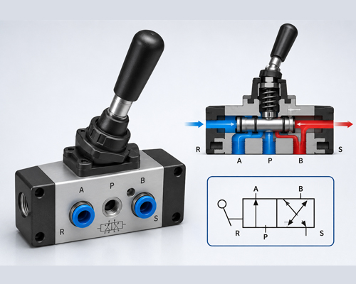
Pneumatic Hand Operated Direction Control Valve
A hand operated direction control valve allows an operator to control compressed air manually through a lever, knob or other operating mechanism. It is suitable for machines where direct manual control is required and electrical actuation is not necessary.
The correct valve should be selected according to its number of ports, positions, port size and operating pressure.
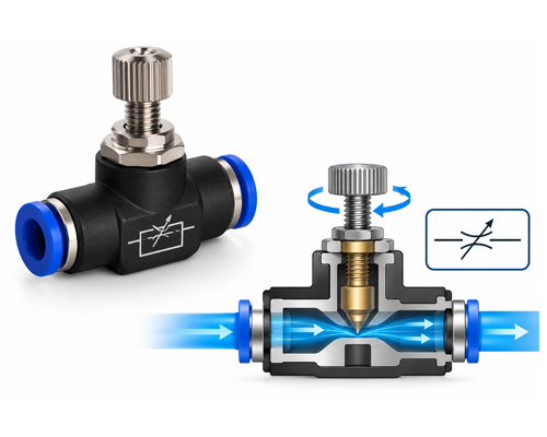
Pneumatic Flow Control Valve
A pneumatic flow control valve regulates the rate at which compressed air passes through the circuit. It is commonly used to adjust the operating speed of pneumatic cylinders and actuators.
The valve must be selected according to the required airflow, tubing size, port connection and direction of control. Depending on the circuit, airflow may be controlled at the inlet or exhaust side of the actuator.
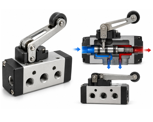
Pneumatic Roller Lever Valve
A roller lever valve is mechanically actuated when a moving machine component contacts the roller. It can be used for position sensing, sequence control and automatic machine operations.
The roller position, operating force, valve configuration and available mounting space should be checked before selection.
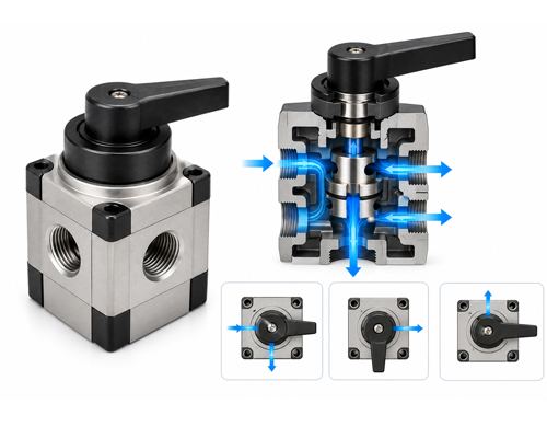
Pneumatic Rotary Valve
A pneumatic rotary valve allows airflow to be controlled by turning an operating handle or selector. It can be used where the operator needs to select between different airflow paths or operating conditions.
The internal port arrangement and number of selectable positions should be matched with the intended pneumatic circuit.
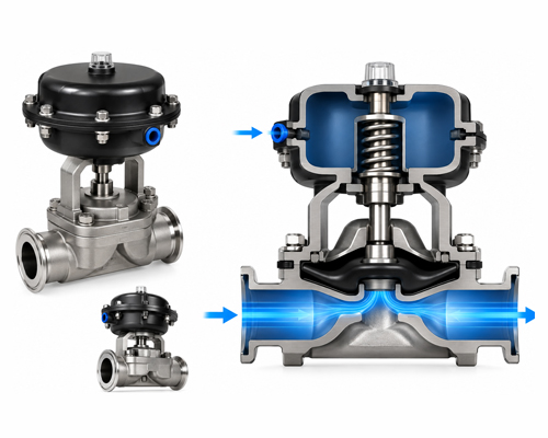
Pneumatic Diaphragm Valve
A pneumatic diaphragm valve uses a flexible diaphragm to control the flow path. The diaphragm separates operating components from the media and supports controlled opening and closing.
Media compatibility, diaphragm material, pressure range, temperature and port size must be confirmed from the product datasheet before installation.
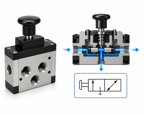
Pneumatic Hand Slide Valve
A pneumatic hand slide valve provides manual control over compressed air by moving a sliding sleeve or internal spool. Depending on the design, it may isolate the air supply and release downstream pressure before maintenance.
The valve should be matched with the required tubing or threaded connection, pressure range and exhaust arrangement.
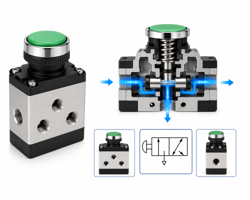
Pneumatic Push Button Valve
A push button valve allows an operator to start, stop or change airflow by pressing a button. It is commonly used for manual machine commands, control panels and simple pneumatic operations.
Push button valves are available in different port and position configurations. The required momentary or maintained operation should be confirmed during selection.
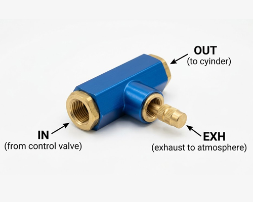
Pneumatic Quick Exhaust Valve
A quick exhaust valve releases air directly near the pneumatic actuator instead of routing all exhaust air back through the directional control valve.
Correct installation can reduce exhaust restriction and help increase cylinder movement speed. The valve size should be matched with the actuator port, tubing size and required exhaust capacity.
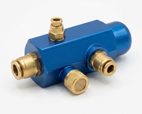
Pneumatic Single Acting Pilot Operated Valve
A pilot operated valve uses an external air signal to shift its internal spool or control element. A single pilot configuration generally uses pilot pressure for actuation and a spring or another return mechanism, depending on the model.
Pilot pressure requirements, return arrangement and port configuration should be confirmed before selection.
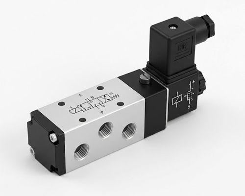
Pneumatic Solenoid Operated Direction Control Valve
A solenoid operated directional control valve uses an electrical signal to change the path of compressed air. It is widely used with control panels, sensors, timers, programmable controllers and industrial automation systems.
Selection should be based on valve configuration, airflow, operating pressure, coil voltage, electrical connection, port size and required response.
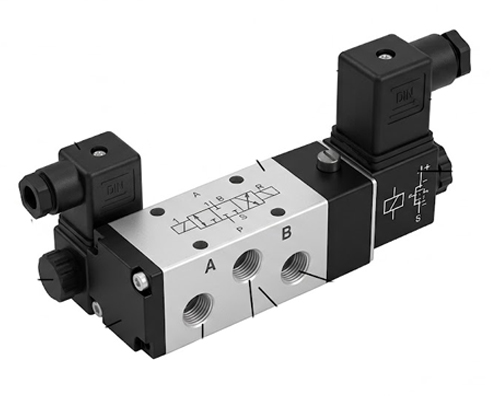
Pneumatic Double Solenoid Valve
A double solenoid valve uses separate coils to shift the valve spool in either direction. Depending on its construction, the spool may remain in its last commanded position until the opposite coil receives a signal.
The control sequence must prevent unsuitable simultaneous coil activation. The exact electrical operation should always be confirmed from the manufacturer’s wiring and technical data.
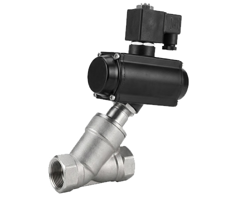
Pneumatic Y Angle Solenoid Valve
A Y angle solenoid valve uses an angled flow path to control compatible air, gas or fluid media. It may be selected where high flow capacity and controlled opening or closing are required.
The media, operating pressure, temperature, body material, seal material and actuation arrangement must be checked carefully for this type of valve.
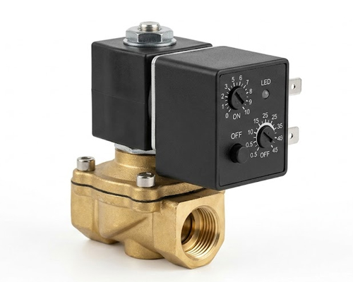
Pneumatic Solenoid Auto Drain Valve with Timer
A solenoid auto drain valve with timer helps discharge collected condensate from compressed air equipment at preset intervals. It may be installed with air receivers, filters and dryers.
The supply voltage, connection size, timer setting, pressure range and condensate conditions should be confirmed before installation.
How Pneumatic Valves Work
Compressed air enters a pneumatic valve through its supply port. An internal spool, poppet or diaphragm then connects or blocks specific airflow passages according to the valve position.
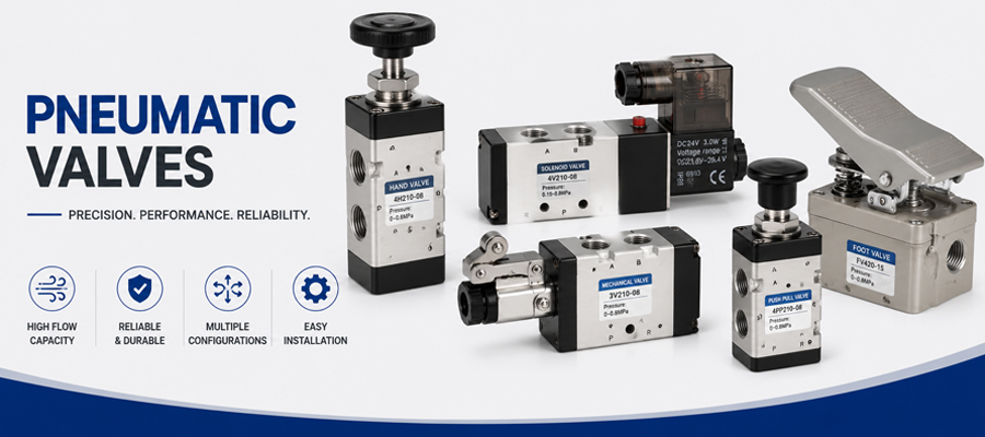
Typical pneumatic valve operation and compressed air flow path.
The internal control element may be shifted through:
- Manual operation
- Mechanical contact
- Electrical solenoid actuation
- Pneumatic pilot pressure
- Spring force
When the valve changes position, compressed air is directed towards the required working port while air from another part of the circuit may be released through an exhaust port.
Not every pneumatic valve remains closed in its normal position. Valves can be normally open, normally closed, spring return, detent operated, single solenoid or double solenoid. The operating behaviour must therefore be confirmed from the valve symbol and technical datasheet.
Common Pneumatic Valve Configurations
2/2 Pneumatic Valve
A 2/2 valve has two ports and two operating positions. It is generally used to start or stop airflow through a line.
3/2 Pneumatic Valve
A 3/2 valve has three ports and two positions. It is commonly used for single acting cylinders, pilot signals and basic air control functions.
5/2 Pneumatic Valve
A 5/2 valve has five ports and two positions. It is commonly used to control the extension and retraction of a double acting pneumatic cylinder.
5/3 Pneumatic Valve
A 5/3 valve has five ports and three positions. Its centre position may be closed, exhausted or pressurised depending on the valve design and application.
The correct configuration depends on the required cylinder movement and the safe condition of the machine when the control signal is removed.
How to Select the Correct Pneumatic Valve
Required Valve Function
First identify what the valve needs to do. The requirement may be directional control, airflow adjustment, supply isolation, quick exhaust, pressure release or automatic condensate drainage.
Number of Ports and Positions
Confirm whether the pneumatic circuit requires a 2/2, 3/2, 5/2 or 5/3 valve. Selecting the wrong configuration can prevent the actuator from operating correctly.
Actuation Method
Pneumatic valves may be manually operated, mechanically operated, air pilot operated or electrically actuated. The available control signal and required operating sequence determine the suitable actuation method.
Port Size and Thread Standard
The port size should support the required airflow without creating unnecessary restriction. The thread type must also match the existing fittings and pneumatic connections.
The thread standard should never be assumed only from the apparent size of the connection.
Operating Pressure
The valve’s rated operating pressure must cover the actual compressed air pressure used in the system. Minimum pilot pressure may also be important for pilot operated and internally piloted solenoid valves.
Airflow Capacity
A valve that is too small can restrict airflow and reduce cylinder speed. A considerably oversized valve may increase cost and air consumption without providing a practical advantage.
Valve flow capacity should be matched with the actuator size, required cycle speed, tubing length and port connections.
Coil Voltage
For solenoid valves, the available AC or DC voltage must match the valve coil. Using an incorrect voltage can cause unreliable operation, coil overheating or premature failure.
The coil duty rating, electrical connector and required enclosure protection should also be confirmed.
Media and Air Quality
The valve materials and seals must be compatible with the media passing through the valve. Industrial pneumatic valves normally require compressed air prepared according to the manufacturer’s recommendations.
Moisture, rust particles, oil deposits and other contamination can affect seals, spools and small internal passages.
Operating Temperature
Both the compressed air temperature and surrounding temperature should remain within the valve’s specified limits. Higher temperatures may require suitable body, seal and coil materials.
Installation Conditions
Mounting direction, vibration, available space, exhaust routing, manifold installation and accessibility for maintenance should be considered before finalising the valve.
Common Reasons for Pneumatic Valve Problems
Pneumatic valve problems do not always mean that the valve itself is defective. The complete circuit should be examined before replacement.
Common causes include:
- Moisture or contamination inside the compressed air line
- Incorrect coil voltage
- Insufficient operating or pilot pressure
- Undersized valve ports or tubing
- Blocked exhaust silencers
- Restricted exhaust flow
- Incorrect valve configuration
- Damaged seals
- Loose electrical connections
- Wrong thread or fitting selection
- Excessive operating temperature
- Incorrect installation orientation
- Mismatch between the valve and pneumatic cylinder
Checking these conditions can prevent repeated valve replacement and unexpected equipment downtime.
Pneumatic Valves for Industrial Applications
Our pneumatic valves are suitable for requirements across different equipment and industries, including:
- Industrial automation systems
- Manufacturing machinery
- Packaging equipment
- Assembly lines
- Material handling systems
- Automobile production and service equipment
- Textile machinery
- Printing and labelling machines
- Food processing equipment where compatible products are specified
- Process equipment
- Pneumatic tools and fixtures
- Machine tools
- Pick and place systems
- Clamping and positioning mechanisms
The final valve specification must be selected according to the conditions of the individual machine.
Pneumatic Valves, Cylinders and Air Preparation
A pneumatic valve should be selected as part of the complete air circuit. Its performance can be affected by the compressor supply, FRL capacity, tubing diameter, fitting size, cylinder volume and exhaust arrangement.
Hydrofit Engineers also supports requirements for:
- Pneumatic Cylinders
- Pneumatic FRL Units
- PU Tubings
- One Touch Fittings
- Pneumatic Quick Release Couplings
- Pneumatic Air Silencers
- Pneumatic Air Tools
- Air Hose Reels
Matching these components correctly can help maintain stable pressure, sufficient airflow and dependable actuator movement.
Why Choose Hydrofit Engineers?
Hydrofit Engineers supports customers with more than product availability. Many enquiries begin with an existing valve photograph, a machine problem or an incomplete model number. Our team helps review the available information and identify a suitable product based on the actual application.
Our strengths include:
- More than 30 years of industry experience
- Wide range of hydraulic and pneumatic products
- Application based product selection support
- Manual, mechanical, pilot and solenoid valve options
- Support for replacement and new machine requirements
- Assistance with regular and bulk industrial quantities
- Chennai based service
- Supply support for customers across India
- Integration support for valves, cylinders, fittings and tubing
Our objective is to help customers select a suitable valve rather than recommend a product only because its port size appears similar.
Information Required for a Pneumatic Valve Enquiry
For a more accurate recommendation, customers should share:
- Existing valve make and model number
- Clear photograph of the valve and nameplate
- Pneumatic symbol printed on the valve
- Required valve function
- Number of ports and positions
- Port size and thread standard
- Operating air pressure
- Required airflow or cylinder size
- Manual, mechanical, pilot or solenoid actuation
- Coil voltage and electrical connection
- Single or double solenoid requirement
- Media and operating temperature
- Machine or application details
- Required quantity
If the model number is unavailable, clear photographs of the valve, connections, coil marking and pneumatic symbol can help with product identification.
Contact Hydrofit Engineers for pneumatic valves in Chennai, pneumatic solenoid valves, directional control valves and industrial air control requirements.
Frequently Asked Questions About Pneumatic Valves
What is a pneumatic valve used for?
A pneumatic valve controls compressed air within a pneumatic circuit. Depending on its type, it can start or stop airflow, change the airflow direction, regulate actuator speed or release exhaust air.
What is the difference between a 3/2 and 5/2 pneumatic valve?
A 3/2 valve has three ports and two positions and is commonly used with single acting cylinders. A 5/2 valve has five ports and two positions and is commonly used to control double acting cylinders.
What is the difference between single and double solenoid valves?
A single solenoid valve uses one coil and commonly has a spring return arrangement. A double solenoid valve uses two coils to shift the spool in opposite directions. The exact operating behaviour depends on the valve model.
Which valve is suitable for a double acting pneumatic cylinder?
A 5/2 directional control valve is commonly used for a double acting cylinder. A 5/3 valve may be required when an additional centre position is needed.
Can a pneumatic valve be selected only by port size?
No. Port size is only one selection factor. Valve configuration, operating pressure, airflow, actuation method, coil voltage, thread type, temperature and application must also be checked.
What does a pneumatic flow control valve do?
A flow control valve regulates compressed air flow and helps adjust the movement speed of a pneumatic cylinder or actuator.
Why is FRL equipment important for pneumatic valves?
An FRL unit helps filter the compressed air, regulate pressure and provide lubrication where the equipment requires it. Correct air preparation can improve valve and actuator performance.
Can a blocked silencer affect valve performance?
Yes. A blocked exhaust silencer can restrict air discharge and reduce cylinder speed. The exhaust path and silencer condition should be inspected during troubleshooting.
Can Hydrofit help identify an existing pneumatic valve?
Customers can share the model number, pneumatic symbol and clear photographs of the valve, coil and port connections. These details can help identify a suitable replacement.