Contact : +91-79045 61980 | Email: hydrofitengineers@gmail.com

Hydraulic Directional Control Valve
A directional control valve is an essential hydraulic valve element of any hydraulic system where it manages the flow path for high pressure fluid with both accuracy and rigidity. Whether you’re designing and building a new machine, or trying to make the most our of your existing hydraulic equipment or hydraulic system performance, sizing the simplest solution is all important. The hydraulic directional control valve forms the backbone of controlled motion, actuation, and automation.
Ranging from simple classic 2/2 directional control valves to high performance 4/3 directional control valves, in-line or manifold mounted (5/2), those minipumps ensure that the desired hydraulic power is directed, bypassed or shut off at the right time and in the right place. Pushing seamless equipment performances throughout industrial, mobile and process-automation environments.
Types of Directional Control Valves
Organizations typically deploy various configurations depending on operational complexity:
- 2/2 directional control valve – Two ports, two positions; ideal for simple on/off flow.
- 3/2 directional control valve – Common in pneumatic and pilot circuits; enables exhaust and supply control.
- 4/2 directional control valve – A robust choice for unidirectional actuator control.
- 4/3 directional control valve – Features three spool positions (open center, closed center, tandem center); widely used in hydraulic power units.
- 5/2 directional control valve – A standard in pneumatic actuator systems; frequently referenced in searches like “5/2 directional control valve is used in” automation processes.
- 5/3 directional control valve – Offers multi-state actuator control for high-precision tasks.
Here is the graphical assets such as a directional control valve diagram or a 4/3 directional control valve diagram enhances system clarity for maintenance and commissioning teams.
Let's understand the directional control valve diagram:
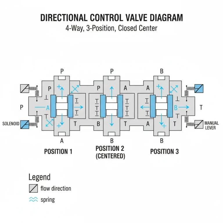
The 4-Way, 3-Position Control Valve: This diagram illustrates the internal mechanics of a (4-Way, 3-Position) 4/3 Directional Control Valve with a Closed Center. This type of valve is the standard “traffic cop” in hydraulic and pneumatic systems, determining the movement of fluid flows.
Here is a breakdown of what the specific symbols and labels represent:
1. The Terminology (“4/3 Closed Center”)
- 4-Way: Refers to the four distinct ports where fluid enters and exits the valve (labeled P, T, A, and B).
- 3-Position: The valve has three distinct states or “positions” it can shift into: neutral (center), left, and right.
- Closed Center: In the middle position (Position 2), all ports are blocked. No fluid flows, which allows the system to hold a cylinder in a fixed position without drifting.
2.The Ports (The Connections)
- P (Pressure/Pump): The supply line where pressurized fluid enters the valve.
- T (Tank/Return): The exhaust line where used fluid is sent back to the reservoir.
- A & B (Work Ports): These lines connect to the actuator (such as a hydraulic cylinder or motor).
3. How It Works (The Three Positions)
The diagram shows the valve spool shifting for the purpose of creating different flow paths:
- Position 2 (Centered): Held in place by Springs, the spool blocks the P, T, A, and B ports. The system is in a “hold” state.
- Position 1 (Actuated): When the Solenoid or Manual Lever is engaged, the spool shifts. Typically, this connects Pressure (P) to Port A, extending the cylinder, while allowing fluid from Port B to drain to the Tank (T).
- Position 3 (Reversed): When actuated in the opposite direction, the flow reverses. Pressure (P) connects to Port B (retracting the cylinder), and Port A drains to Tank (T).
How a Directional Control Valve Works?
A directional control valve determines which way hydraulic fluid flows in a system. When the operator actuates the actuation mechanism, which could be manual, solenoid, pilot-operated or mechanical – internal spool moves. This movement opens or closes, and channels passages for a fluid.
With more complex configurations, such as a pilot-operated direct control valve, the spool movement is actuated using pilot pressure to provide high-flow performance with low actuation force.
Knowledge of the internal directional control valve symbols and standardized ISO diagrams is key to efficient system design, troubleshooting and documentation. They’re showing how flows cross state lines- whether a 4/2 directional control valve or 3/2 directional valve symbol. For example, or a graphically articulated 4/3 directional control valve symbol that includes all three spool positions.